Assembly
Preparing the PCB
The NTS-1 Custom Panel reference board is open hardware and all source/description files are available on GitHub.
The PCB Gerber data can be used as-is to order bare boards from a PCB manufacturing service near you.
The provided KiCAD project can be used as a starting point to create your own custom panel designs.
Acquiring Parts
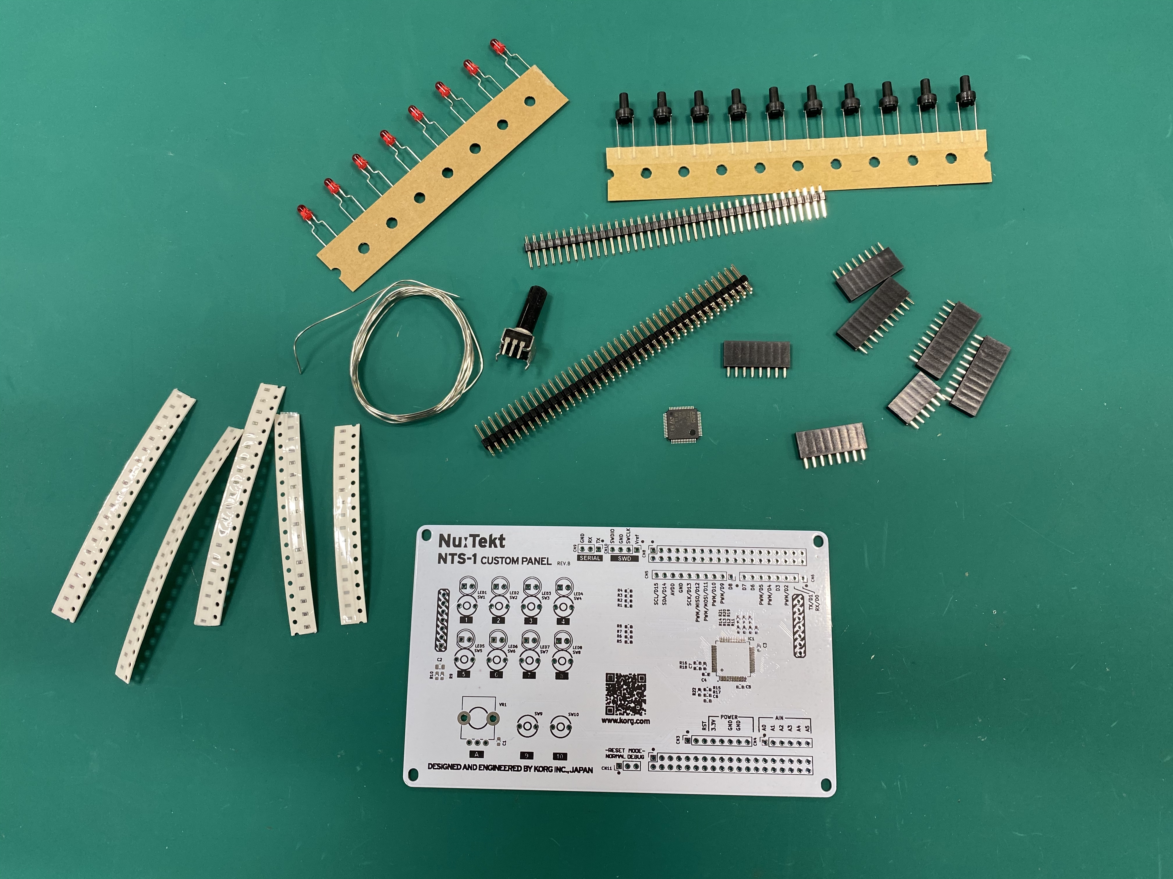
The following parts are necessary to fully mount the reference board.
Full bill of materials: PDF, Excel
Tip: The Excel file can be uploaded directly to Mouser to automatically fill your cart with the appropriate parts.
| Manufacturer | Description | Qty | Datasheet |
|---|---|---|---|
| Yageo | Thick Film Resistors - SMD ZERO OHM JUMPER | 1 | datasheet |
| Yageo | Thick Film Resistors - SMD 33 OHM 5% | 1 | datasheet |
| Yageo | Thick Film Resistors - SMD 47 OHM 5% | 4 | datasheet |
| Yageo | Thick Film Resistors - SMD 220 OHM 5% | 8 | datasheet |
| Yageo | Thick Film Resistors - SMD 100K OHM 5% | 1 | datasheet |
| Yageo | Thick Film Resistors - SMD 10K OHM 5% | 4 | datasheet |
| Yageo | Thick Film Resistors - SMD 1K OHM 5% | 2 | datasheet |
| Yageo | Thick Film Resistors - SMD 47K OHM 5% | 1 | datasheet |
| KEMET | Multilayer Ceramic Capacitors - SMD 16V 0.1uF 0603 X7R 10% | 4 | datasheet |
| KEMET | Multilayer Ceramic Capacitors - SMD 16V 1000pF 0603 X7R 10% AEC-Q200 | 2 | datasheet |
| KEMET | Multilayer Ceramic Capacitors - SMD 16V 1uF X5R 0805 10% | 1 | datasheet |
| TE Connectivity | Headers & Wire Housings 38 MODII HDR DRST UNSHRD .100 | 2 | datasheet |
| TE Connectivity | Headers & Wire Housings 1X02P RCPT HV-100 TE | 1 | datasheet |
| TE Connectivity | Headers & Wire Housings 6P RECPT VERT HV-100 | 1 | datasheet |
| TE Connectivity | Headers & Wire Housings 8P RECPT VERT HV-100 | 2 | datasheet |
| TE Connectivity | Headers & Wire Housings 1X03 POS VERT TIN | 2 | datasheet |
| TE Connectivity | Headers & Wire Housings 1X04 POS VERT TIN | 1 | datasheet |
| Omron | Headers & Wire Housings Sensor I/O Connector | 2 | datasheet |
| Kingbright | Standard LEDs - Through Hole 5mm Red LED 640nm | 8 | datasheet |
| ALPS | Potentiometers 10 KOhms 20% | 1 | datasheet |
| ALPS | Tactile Switches RND 6.0x4.3mm 100gf | 10 | datasheet |
| STMicroelectronics | ARM Microcontrollers - MCU Value-Line ARM MCU 64kB 48 MHz | 1 | datasheet |
| TE Connectivity | Headers & Wire Housings 2 POS POST SHUNT | 1 | datasheet |

Soldering
Once all parts of the BOM have been acquired, refer to the schematic and mount diagram, and solder each part to its appropriate location on the PCB.
Soldering Tutorials
There are many tutorials all over the internet, however not all of them cover surface mount devices which are required for the NTS-1 Custom Panel.
The tutorial videos below do cover everything you need:
- EEVblog Soldering Tutorial Part 1: Tools
- EEVblog Soldering Tutorial Part 2: Through Hole
- EEVblog Soldering Tutorial Part 3: Surface Mount
Assembling
After completing the soldering, remove the interface panel of the NTS-1 digital kit and replace it with the custom panel.
Note: NTS-1 main system has to be updated to at least version 1.10 in order to work with custom panels. Confirm the firmware version and update if needed before replacing the panel.
Note: NTS-1 digital kit firmware version 1.10 will be released towards the end of February 2020.