Programming
Choosing a Board Programmer
The reference custom panel uses a microcontroller (STM32F030R8) to scan for user interactions and communicate with the NTS-1 digital kit’s main board. The most convenient way to program this microcontroller is via the exposed SWD (4-pin) connector using an ST-LINK (or compatible) chip programmer, here are some examples:
- Nucleo board with built-in ST-LINK: NUCLEO-F030R8
- Standalone ST-LINK: STLINK-V3SET
- OEM ST-LINK compatible USB dongles: i.e: amazon
Caution! Many OEM programmer dongles provide 3.3V on the Vref pin instead of monitoring it for reference voltage as they should, make sure NOT to connect the Vref pin of such programmers. Use a voltmeter to check the Vref pin of the programmer, if you detect a voltage on it do NOT connect it to the reference custom panel board. Official ST-LINK programmers do not have that problem.
Female-female DuPont pin cables with 2.54mm pitch will also be required to connect your programmer to the SWD pins of the reference board (sometimes provided with the programmer). Depending on the programmer you use the SWD pins of the reference board may not be in the same order, carefully read your programmer’s manual and make sure you connect the pins in the right order. (splitable or individual pin cables may be useful if you need to reorder the connections)
Connecting the Programmer
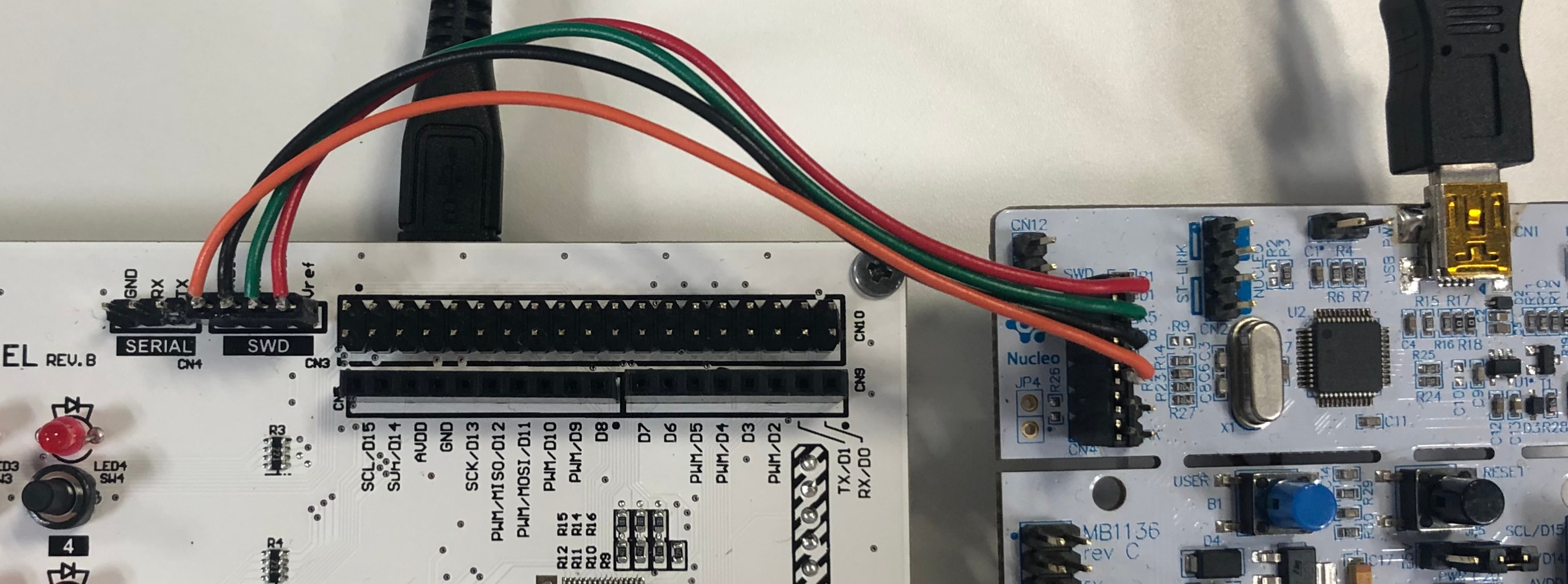
The ST-LINK compatible programmer should be connected to the SWD connector in the following way:
Preventing Panel Reset
While programming and generally during firmware development, it is recommended to prevent the reference custom panel from being reset by the NTS-1 digital kit’s main board when communication timeouts occur.
To prevent panel resets, set the jumper on connector CN11 to the DEBUG position.
The jumper can be placed back into the NORMAL position when simply using the NTS-1 digital kit with the custom panel.
Programming with the Arduino IDE
An Arduino board definition package is provided for the reference custom panel, which allows to build firmwares from Arduino Sketches and program the microcontroller via the Arduino IDE. The board definition handles the low level details of the communication with the NTS-1 digital kit’s main board, providing a high level interface suitable for fast prototyping.
Requirements
The following softwares must be installed:
Setting Up the Board Definition
- In the Arduino IDE, open the Preferences from the File menu
- Open the Additional Boards Manager URLs editing window
- Add the following URL to the list:
https://raw.githubusercontent.com/korginc/nts-1-customizations/master/Arduino/package_nts1_custom_panels_index.json
- Click OK for both windows, and open the Boards Manager from the Tools > Board: menu
- Search for NTS-1 Custom Panels and install version 1.0.0
- Select NTS-1 Custom Panels from the Tools > Board: menu in the NTS-1 Custom Panels group
- Make sure the board listed in Tools > Board part number: matches your board.
Serial Monitoring
Monitoring via the built-in Arduino Serial object is possible by using a USB-Serial adapter (based on FTDI RS232 chip), such as this one or this one.
Caution! The NTS-1 Custom Panel Reference Board is not 5V tolerant. Please do NOT connect 5V powered device. USB serial adapters sometimes have jumpers to select 3.3V or 5V operation mode, make sure to set it to 3.3V.
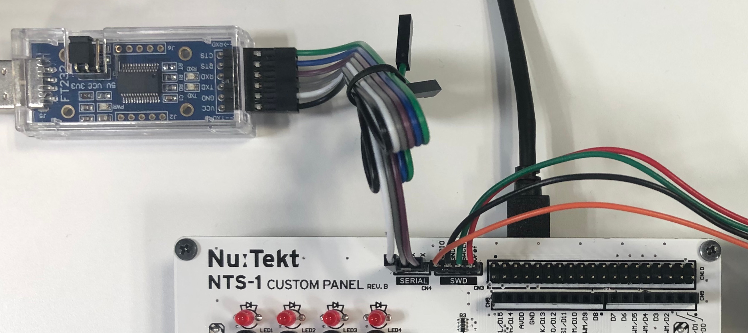
Connect the USB-Serial adapter to the SERIAL connector in the following way:
If using the Arduino IDE serial monitor, select the COM port corresponding to the USB-Serial adapter in the tools > port menu. External serial monitoring software can also be used, in which case refer to that software’s documentation.
Example Sketches
Some examples Arduino Sketches are provided as starting points for your own projects:
- Blank Template: bare minimum code required to build a Sketch with the NTS-1 Custom Panel board definition.
- Sequencer Template: basic 8 step sequencer with user interface scanning and LED control implemented via timer driven interrupts
You can find the templates in the File > Examples > NTS-1 menu.
Verify and Compile
You can compile your Sketch without uploading it to the board by pressing the Verify button, or by selecting Verify/Compile in the Sketch menu.
Upon success you should see something like the output below in the Arduino IDE console.
 Sketch uses 10832 bytes (16%) of program storage space. Maximum is 65536 bytes.
 Global variables use 2112 bytes (25%) of dynamic memory, leaving 6080 bytes for local variables. Maximum is 8192 bytes.
Uploading and Running
Once all prior steps have been completed. You can build and upload an Arduino Sketch to the reference custom panel board this way:
- Make sure Tools > Upload Method: is set to SWD.
- Press the Upload button, or select Upload from the Sketch menu.
Upon successful programming of the board you should see something like the output below in the Arduino IDE console:
      -------------------------------------------------------------------
                       STM32CubeProgrammer v2.2.0
      -------------------------------------------------------------------

    ST-LINK SN  : 066AFF535550755187255039
    ST-LINK FW  : V2J34M25
    Voltage     : 3.27V
    SWD freq    : 4000 KHz
    Connect mode: Under Reset
    Reset mode  : Hardware reset
    Device ID   : 0x440
    Device name : STM32F05x/F030x8
    Flash size  : 64 KBytes
    Device type : MCU
    Device CPU  : Cortex-M0

    Memory Programming ...
    Opening and parsing file: Blank_Template.ino.bin
        File          : Blank_Template.ino.bin
        Size          : 11056 Bytes
        Address       : 0x08000000

    Erasing memory corresponding to segment 0:
    Erasing internal memory sectors [0 10]
    Download in Progress:

    File download complete
    Time elapsed during download operation: 00:00:00.982

    RUNNING Program ...
        Address:      : 0x8000000
    Application is running
    Start operation achieved successfully
Other Programming Methods
It is possible to program the reference custom panel directly using the STM32 Cube Programmer software from STMicro, or any other compatible programming/on-chip debugger software (i.e.: OpenOCD), however it will be necessary to install toolchains on your own and build the firmware from scratch.
Low level information about the communication protocol with the main board will be provided at a later date.